In an effort to understand the information obtainable through the Leap Motion controller, I tested out the functionality using the Software Development Kit's (SDK) visualization program. It provides a decent interface for understanding and visually showing information the controller is receiving. Before I talk about what sort of information I am able to receive, it is probably useful to discuss some basic information about the structure of the hand and its phalanges (fingers):
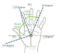 |
| Phalangeal Range of Motion |
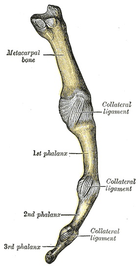 |
| The Finger Structure |
The hand has a very complex structure permitting a wide range of motion to each of its appendages. Additionally, each finger has its own motional complexity. The finger can divided into three phalanges bones that are connected by collateral ligaments. Ligaments are the tissues that connect bones to other bones. In the case of the finger, they provide the mechanism of joints. As an example, in the figure on the left, the collateral ligament between the metacarpal bone and the 1st phalanx forms what is typically called the 'knuckle'.
From the finger structure, there exist three possible joints that theoretically can be independently moved. This is the case for all of the fingers. The thumb, however, only has a knuckle joint and one additional joint connecting its two phalanges. That is not to say that the thumb is less complex. Its opposability gives it a much larger range of motion and thereby greater complexity.
Returning to the Leap- I used their visualization that depicts effectors as cylinders. The basic method displays them as vectors in 3D space, but that is not as helpful when analyzing movements relative to each finger. The cylindrical representation also makes it easier to see relative lengths of the fingers (widths, unfortunately, do not currently reflect the actual widths of the fingers).
There is a good amount of information that can be visualized (as well as received in terms of data from the Leap). In particular, it is possible to see the palm normal of the hand. When moving the separate fingers, this information is useful because we can tell how fingers can move relative to a (presumably) stationary plane. Angle calculations, at the very least, can be made with respect to the knuckles.
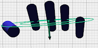 |
| Palm Normal |
 |
| Fingers Visualized as Cylinders |
There is an interesting problem to solve in terms of how the direction of the effector (the finger vector) can be used to achieve the joint angles present along the other two bend angles on each of the fingers (and the one angle of the thumb).
To begin, I will most likely assume that the joint angle move in sync. This assumption will allow me to interpolate bend angles along the finger to at least get a working prototype. From there, I will attempt to find a mechanism for achieving better estimates of all of the joint angles. This may result in the use of multiple Leap devices to capture information from different view angles.
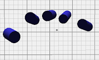
Another bit of information that is potentially useful in detecting joint angles is the palm sphere radius. This works by estimating the radius of a spherical object that could be held by the hand. A closed hand produces a smaller sphere radius while a large one produces a larger radius. This information is useful because a smaller radius implies a closed hand, thereby the fingers must be angled downward. I'm not sure how this can be used for joint angles, but that is something I will find out. I will end here with some goals for this week:
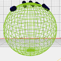 |
| Open Palm |
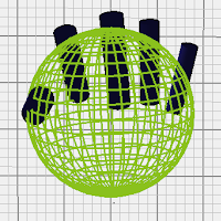 |
| Closed Palm |
- Finish my proposal for Project PAALM.
- Start reading through the research on hand motion detection devices and hand tracking.
- Start working on a prototype that will at least give some information about estimated joint angles. I will work towards just visualizing and estimating angles for a single finger (probably the index).


